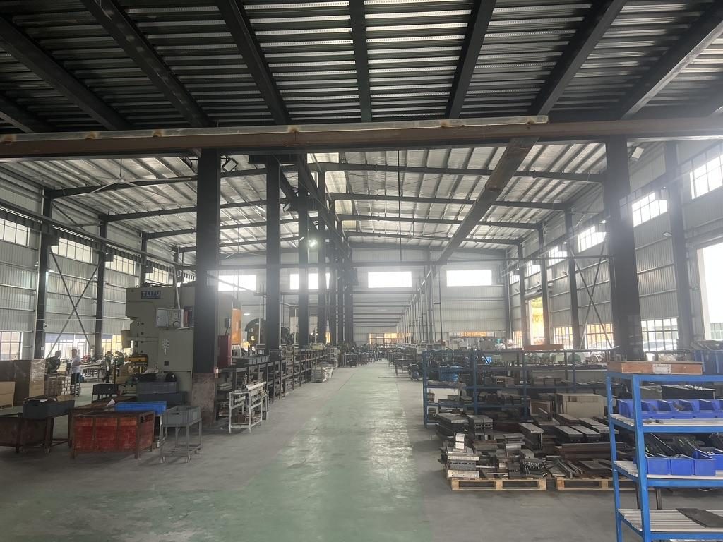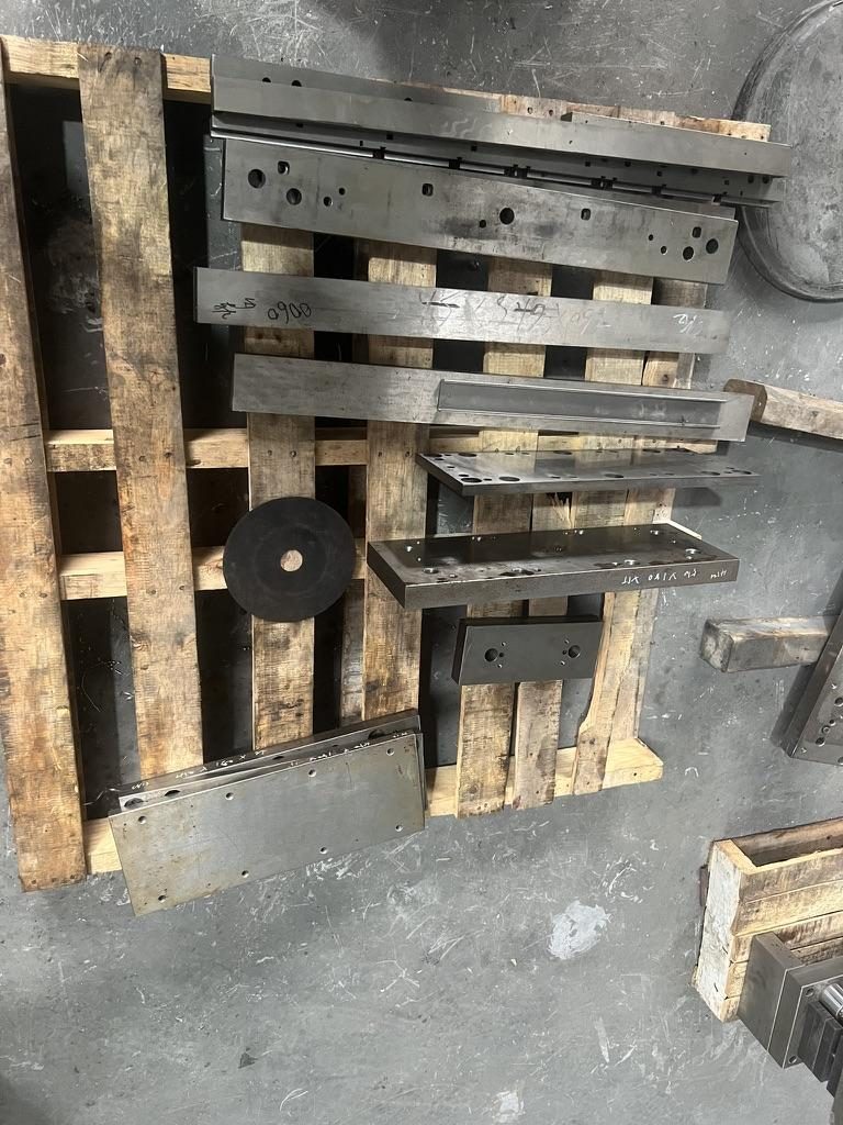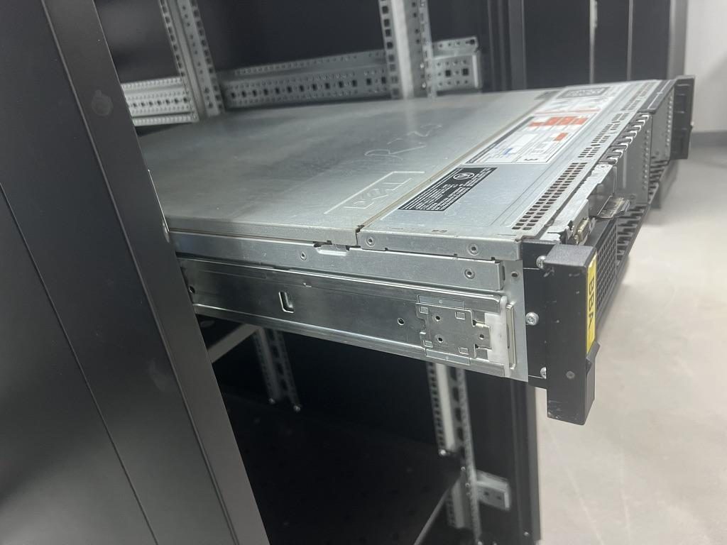

A step-by-step, photo-guided factory tour showing how server rails are made — materials, roll-forming and progressive stamping with custom dies, machining and welding, finishing, testing and packing under an ISO 9001:2015 quality system.
Materials, Design Specifications and Tolerances
Choosing the right metal and the right dimensional strategy is where a rail succeeds or fails in the rack — it governs manufacturability, stiffness, install fit and long-term serviceability.
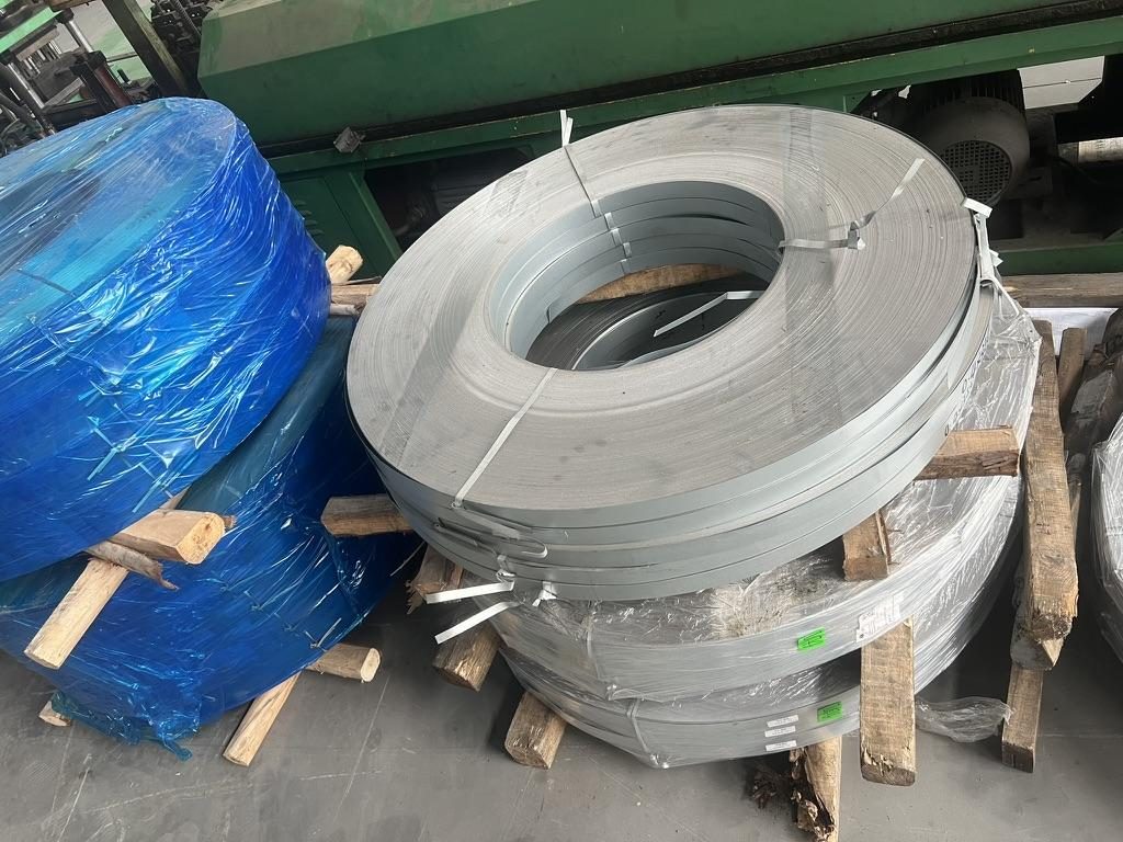 Cold-rolled steel coil, the raw material for server rails
Materials and trade-offs
- Cold‑rolled carbon steel: the most commonly used substrate for stamped and roll‑formed rails because it balances cost, formability and stiffness for rails that will be plated or powder‑coated.
- Low‑alloy steels: used when slightly higher yield strength or toughness is needed while keeping stamping/roll‑forming behavior close to CR steel.
- Stainless steel: selected where corrosion resistance and electrical continuity without plating is required; more difficult and costly to stamp.
- Aluminum (often extruded): used when weight and corrosion resistance are primary drivers; extrusion produces integrated profiles but requires secondary operations for hole patterns or brackets.
What matters to engineers (not marketing claims)
- Match material to the manufacturing path: roll‑forming and progressive stamping favour ductile cold‑rolled steels; extrusion suits aluminum profiles.
- Stiffness and section geometry interact: a thinner section on the drawing will often need ribs, embosses or local thickening at mount points and keyholes to control sag and fatigue.
- Surface treatment affects electrical contact and fit: plated steel plus powder coat changes contact resistance and layer thickness — specify uncoated landings or tapped‑after‑finish where grounding or threading is critical.
Hole patterns, rack interface and standards
- “19‑inch” (IEC/EIA classification) denotes the front‑panel width family (482.6 mm) but does not guarantee hole type, thread or mounting depth. Always confirm:
- Rack hole type (square punched for cage nuts, round, or threaded 10‑32 / 12‑24, etc.).
- Exact hole sizes and datum locations — common customer drawings we review often show square 9.5 × 9.5 mm or round Ø7.1 mm holes, but confirm with the rack owner.
- Actual post‑to‑post distance and the bracket fit range you expect the rail to span — closed/extended rail lengths are different drawings values and do not substitute for the real mounting‑depth measurement.
- Chassis interface: T‑pin (PEM) head and shaft diameters, under‑head clearance and pin spacing must be supplied. Derive keyhole/J‑slot geometry from the pin dimensions rather than assuming a universal shape.
Definitions engineers rely on (MetrixSlide practice)
- Closed length: the rail’s overall length when fully nested/closed.
- Extended length (or full extension): the length when a specified extension or full travel is reached.
- Bracket fit range (mounting depth range): the span the rail’s brackets will accommodate between front and rear posts — this is the number you must give to vendors for fit checks.
- Per‑pair static full‑extension rating: the static load capacity specified for one pair of rails at the stated extension condition (a common way to express rail capacity).
Practical tolerance guidance for engineering handoff
- Define critical datums (front face, mounting plane, pin centres) on the drawing you send to suppliers, and mark features that are “fit‑critical” (e.g., hole‑to‑hole centres, pin centres) vs “assembly‑tolerant” (non‑mating flanges).
- Suppliers typically confirm workable manufacturing tolerances during the CAD review and a first‑article inspection (FAI). MetrixSlide engineering practice follows the decision rule: compatibility hard gates before preferences — confirm chassis and rack interfaces and load first, then optimise mechanism and finishes.
- Finer capability signals can include a factory-side stamping precision claim as low as 0.08 mm absolute error. Treat such numbers as capability statements that require FAI confirmation.
Key factory capabilities and examples
- MetrixSlide works with an ISO 9001:2015‑certified slide‑processing factory (scope: processing of metal products / slides). Certification indicates an established quality system for slide processing; it is not a substitute for part‑level validation.
- Examples from recent projects:
- A North American telecom OEM reviewed a 1U friction slide family where rack post distances in the supplied draft ranged from 674 ±3 mm to 919 ±3 mm and the requested pull‑out specification was reduced from a legacy 300 mm to about 150 ±3 mm for load‑stability reasons.
- An Indian HPC ODM specified a bracket fit range of 650–965 mm for a 2U ball‑bearing solution; the customer’s typical post distance that the range needed to cover was about 812 mm.
- A Korean surveillance‑equipment maker evaluated an ultra‑slim 4U NVR rail with a 440 mm chassis body and asked for a thin‑section solution (the customer indicated a wish to explore ≤5 mm material thickness).
- A SaaS company building its own servers supplied PEM T‑pin data (example PEM SKS‑R1.5‑4‑0: head 6.502 mm / shaft 4.00 mm / under‑head clearance 1.585 mm) so we could derive J‑slot geometry rather than guessing.
- Heavy‑duty example: MetrixSlide’s model MS-BBR-180 has a nominal capacity of up to 180 kg per pair, and a formal test report at that load is not yet available; in the factory static‑load test a rail pair is held under load at full extension for 24 hours, and the MS‑FMR‑2U‑100 held 100 kg in that test.
Forming, Stamping and Tooling Processes
How a flat coil becomes a formed, feature‑rich rail depends on the geometry, run volume and required tolerances.
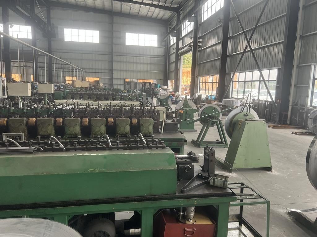
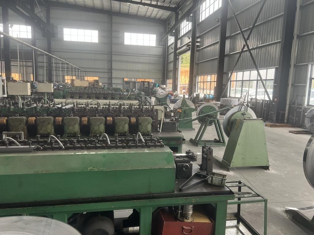 Roll-forming line with decoiler feeding cold-rolled strip
Main forming options and when to use them
- Roll forming (continuous bending): best for long, uniform steel profiles with repeated bends and flanges. Low scrap and fast per‑metre throughput at medium‑to‑high volumes. Roll dies allow progressive positioning of flanges and bend features along the part length.
- Progressive stamping (progressive dies): ideal when many punched features, complex cutouts, embosses and formed details must be produced in a controlled hole‑to‑hole relationship. Very economical at high volume but requires higher NRE for dies.
- Extrusion: for constant cross‑section aluminum rails where the profile shape cannot be efficiently formed from sheet. Extruded profiles need secondary operations for holes, brackets or special mounts.
Tooling design and die practices (MetrixSlide engineering practice)
- Progressive dies are designed around a forming sequence (piercing → drawing → bending → trimming). Key elements include lead‑in chamfers, material draw compensation and a strip layout that minimises waste.
- For roll forming, validate minimum bend radii for the chosen steel grade and thickness and control strip guidance to avoid lateral displacement of pierced features.
- Where flexibility is needed across similar products, consider modular die stations or shared tooling to reduce NRE amortisation.
Shopfloor practices often omitted in marketing
- Stress relief and straightening are commonly applied after stamping to release springback before precision machining or assembly.
- Flat pattern and bend‑compensation calculations should be supplied and verified against the supplier’s machine‑specific k‑factors; request developed‑length verification during the CAD review.
- Die maintenance and a preventive cadence are essential for dimensional stability across a production run.
Comparison at a glance (process choice checklist)
- Roll forming: choose for long steel profiles with repetitive bends and medium‑to‑high volumes.
- Progressive stamping: choose when many precise punched features and cutouts are required at high volume.
- Extrusion (aluminum): choose for constant profiles and when the geometry justifies extrusion tooling.
Machining, Welding and Assembly Methods
After forming and punching, rails move to value‑add machining and final assembly. The choice of joining and fixture design determines straightness, repeatability and yield.
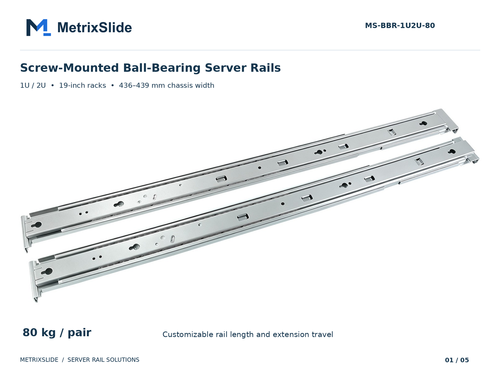 MS-BBR-1U2U-80 Screw-Mounted Ball-Bearing Server Rails — view product
Precision machining and fixturing
- Secondary ops typically include reaming, countersinking, slot milling and tapping on CNC stations with fixtures that index to the stamped datums.
- Good fixture design locates by primary stamped datums and clamps to prevent distortion during machining or welding.
Welding and distortion control
- Spot (resistance) welding is common for sheet steel assemblies when many discrete weld points are needed with low heat input.
- MIG/TIG are used for continuous seams or stainless‑steel joins—choice depends on material and deformation budget.
- Distortion control measures include planned weld sequences (stitching or alternating sides), temporary clamps and post‑weld straightening jigs.
Assembly strategies: prototype vs production
- Prototypes: rivets, screws and structural adhesives avoid weld heat and reduce NRE while validating fit.
- Production: spot or seam welding with validated jigs improves throughput and repeatability; invest early in assembly jigs that replicate the rack‑mounted datum to keep final geometry consistent.
Production rhythm and order sizing
- Routing depends on batch size: small runs use manual assembly; medium/large runs favour semi‑automation and dedicated jigs.
- In MetrixSlide project practice, sample pairs for physical validation commonly ship roughly 15–20 days after drawing approval for small prototype quantities — use this as a planning input and confirm lead times for each project.
Finishing, Corrosion Protection and Sustainability
Finishing is not just cosmetic — it affects lifetime, grounding, assembly fit and recyclability.
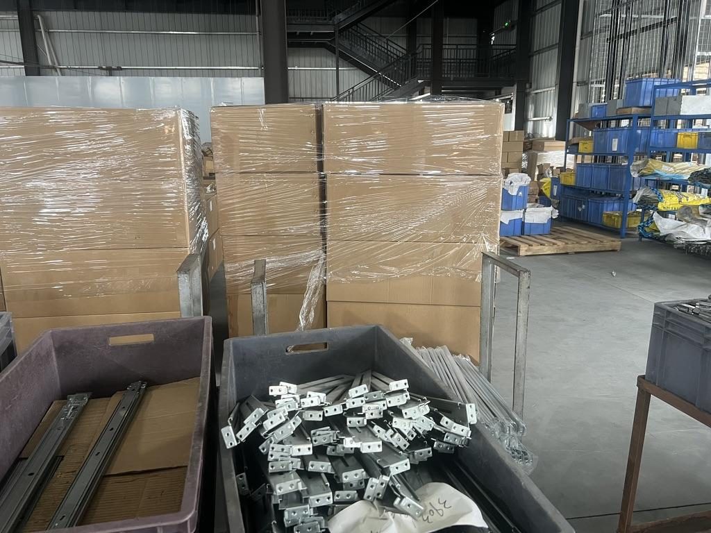 Finished server rails being packed for shipment
Common finishes and practical effects
- Electro‑zinc plating (with or without organic seal): economical, compatible with powder coating. For tapped holes, specify tapped‑after‑finish or accept re‑tapping post‑plating.
- Phosphate + powder coat: widely used in data‑center rails for a durable, even finish.
- Anodizing (aluminum) or chemical passivation (stainless): preserve base‑metal corrosion resistance without electroplating.
Design and maintenance implications
- Coating thickness affects tolerances and thread engagement — call out tapped‑after‑finish where engagement matters.
- For typical data‑centres, coatings protect against incidental corrosion; humid or harsh environments may require heavier or sealed systems.
- Sustainability: select RoHS/REACH‑screened chemistries and prefer single‑material assemblies where end‑of‑life recycling is a concern.
Quick‑turn finishing
- For rapid prototypes, uncoated or lightly passivated parts with local bare grounding lands can help meet tight schedules; advise customers on interim corrosion protection during storage.
Quality Control, Load Testing and Production Economics
Quality systems, testing protocols and economic levers determine whether a rail will install and perform in the field.
Quality gates and inspection
- Incoming material checks should include material certificates and sample verification.
- First Article Inspection (FAI) validates critical datums and hole patterns before production release.
- In‑line checks: fixture audits, periodic dimensional sampling and surface‑finish checks during runs.
Load testing and validation (MetrixSlide practice)
- Define ratings precisely: per pair or per rail, static vs dynamic, extension condition (closed/partial/full), fixture and duration.
- In the MetrixSlide factory static‑load test a rail pair is held under load at full extension for 24 hours (not a universal industry standard), and the MS‑FMR‑2U‑100 held 100 kg in that test.
- Dynamic cycle testing validates life‑cycle behaviour of mechanisms (bearings, friction pads, locks); specify cycle counts and fixture replication representative of the rack mounting conditions.
Production economics — what drives price
- Largest drivers: material cost (choice and thickness), tooling amortisation (progressive dies or roll tooling), processing time (complex stamping, CNC, hand assembly) and surface treatment choices.
- Design strategies to reduce cost without sacrificing function:
- Remove non‑structural material on wide flanges and add embossed ribs or formed stiffeners where needed.
- Standardise hole patterns across product families to allow shared tooling.
- Specify which features are install‑critical so suppliers can relax less important tolerances.
Decision rules and workflow (MetrixSlide engineering flow)
- Requirement → CAD → physical fit → performance. Passing a CAD fit review does not guarantee final performance; physical samples and load validation are mandatory hard gates.
- Selection order checklist (hard gates before preferences):
- Chassis inputs (U height, width, depth, mount features).
- Rack inputs (hole type, actual post spacing or range).
- Compatibility hard gate (do interfaces match?).
- Load hard gate (per‑pair/rail target and extension state).
- Architecture choice (sliding/fixed, ball‑bearing/friction, tool‑less).
- CAD → sample → physical validation → production release.
Form & Fit Taxonomy (quick reference)
- Motion: fixed vs sliding.
- Mechanism: ball‑bearing vs friction.
- Mounting: tool‑less vs screw‑mount; installation style: stab‑in vs drop‑in.
- Sections: two‑section, three‑section (inner/middle/outer).
- Parameters to specify: bracket fit range, closed/extended lengths, pull‑out/lock‑out distance, per‑pair static rating.
Real project vignettes (anonymised, engineering figures from project data)
- North American telecom OEM: a 1U friction slide project used post distances in the draft of 674 ±3 mm to 919 ±3 mm and a reduced pull‑out lock‑out target of about 150 ±3 mm instead of a legacy 300 mm to improve load stability at extension.
- Indian HPC ODM: specified a bracket range of 650–965 mm to cover ~812 mm typical post spacing for their 2U servers when choosing a ball‑bearing solution.
- Korean surveillance‑equipment maker: evaluated an ultra‑slim 4U NVR rail with a ~440 mm chassis body and a request to explore thinner rail sections (customer indicated interest in ≤5 mm material).
- SaaS server builder: provided PEM T‑pin data (example SKS‑R1.5‑4‑0: head 6.502 mm / shaft 4.00 mm / under‑head clearance 1.585 mm) so the J‑slot geometry was derived from the pin, avoiding trial‑and‑error.
Note on capability claims and evidence
- Some capability signals (for example, a 0.08 mm stamping absolute‑error claim and the 24‑hour static‑load test) should be validated by FAI/test reports before being quoted as a guaranteed performance level.
Conversion / CTA
If you’re designing rails into a server or rack, send three quick items for a fast, accurate response: (1) a 2D drawing or 3D STEP of the chassis mounting area, (2) the rack post‑to‑post distance or bracket fit range and hole type, and (3) expected static load per pair and target annual quantity. We’ll return a rail‑matching proposal with drawings, lead‑time estimate and sample options. Typical small‑change customizations (bracket position, hole pattern, length, thickness) usually carry no tooling fee — structural redesigns may incur NRE. Start here: https://www.metrixslide.com/contact-us/ or get an instant quote at https://www.metrixslide.com/page/create-a-quote/.
FAQ
Q: Which steel grades and thicknesses are most commonly used for 19" server rack rails and how do they affect load capacity? A: Most server rails are made from cold‑rolled carbon steel for its combination of formability and stiffness; stainless steel and aluminum are used where corrosion or weight are higher priorities. Thickness and cross‑section determine stiffness and sag — specify the maximum static load (per pair), extension condition and chassis width to let the manufacturer recommend a suitable material/thickness combination and any needed stiffening features.
Q: What dimensional tolerances and hole‑pattern specifications are needed to comply with EIA‑310 for rack‑mounted equipment? A: EIA/IEC define the 19‑inch class but not every hole type or mounting depth. Provide the exact rack hole type (square punch, round, threaded) and the hole datum locations; common hole sizes we encounter include square 9.5 × 9.5 mm and round Ø7.1 mm. Mark fit‑critical features on your drawing (pin centres, front datum) and let the supplier confirm hole‑to‑hole tolerances during FAI.
Q: When should a manufacturer choose roll forming, stamping or extrusion for producing rails, and what are the cost/volume trade‑offs? A: Choose roll forming for long steel profiles with repetitive bends at medium‑to‑high volumes; progressive stamping when many integrated punched features and close hole tolerances are needed at high volume; extrusion for aluminum constant profiles when geometry justifies the extrusion tooling. Tooling and die amortization drive economics — engage manufacturing early so process choice aligns with your target quantity and budget.
Q: What welding and assembly methods minimize distortion and maintain rail straightness during high‑volume production? A: Use spot welding with well‑designed fixtures and a planned welding sequence to balance heat. Where continuous welds are required, stitch welding, alternating weld sides and post‑weld straightening jigs reduce distortion. For low‑volume prototypes, rivets, screws or adhesives avoid heat and let you validate fit before investing in welded assembly tooling.
Q: How are static and dynamic load tests for server rails performed, and what safety factors are typically applied? A: Static tests hold the specified load at the stated extension for a defined time period to check for permanent set or sag — heavy rails often undergo extended 24‑hour static holds during validation. Dynamic tests cycle the rail through seating, extension and retraction to reproduce expected service cycles. Safety factors and acceptance limits are defined per customer spec; include extension condition (closed/extended), per‑pair vs per‑rail basis and fixture details when requesting a validated rating.
Talk to a MetrixSlide engineer
Not sure how this applies to your servers? Send us a chassis drawing or model (STEP or DWG), the rack post-to-post distance and hole type, the expected load and your planned quantities. Within 24 hours you get a rail matching proposal from an engineer, followed by 2D/3D drawings for review and sample pairs (typically 15–20 days after drawing approval) for physical validation before the full order.
Bracket position, hole pattern, rail length and thickness adjustments on our existing platforms usually carry no tooling fee; structural redesigns are quoted separately with dies made in-house.