
A practical, engineer‑level guide to how suppliers validate static load capacity, measure hole‑position accuracy, preserve drawing revision history and meet ISO‑level traceability for rack rails.
Defining maximum static load capacity for server rails
"Static load capacity" is the load a rail (or pair of rails) is rated to support when that load is applied slowly and held in place — distinct from dynamic or impact loads during insertion, transport or seismic events. A valid load rating must identify whether it applies per pair or per individual rail and the loading/extension condition used to produce the rating.
Key MetrixSlide baseline and interpretation
- Model baseline: MS-BBR-180 has a nominal capacity of up to 180 kg per pair; a formal test report at that load is not yet available. Any load figure must always be interpreted together with the referenced test condition (pair vs rail, extension state, fixture and duration).
- "Per pair" vs "per rail": unless the supplier explicitly states otherwise, a per‑pair rating refers to the combined capability of the left + right rail pair as used in a rack installation. A simple per‑rail estimate is often half the pair value, but multi‑pair sharing and mounting geometry can change how loads distribute and must be validated for the real assembly.
Units and conversions (for convenience)
- 1 kg = 9.80665 N; 1 lb = 4.44822 N; 1 kg ≈ 2.20462 lb.
Interpretation guidance (engineering practice)
- Always ask for the evidence that underlies a published number: which model/configuration was tested; was the figure per pair or per rail; was the rail closed, partially extended or fully extended; was the test static and for how long; and what fixture/mounting and acceptance criteria were used. If that evidence is absent, treat a single numeric label as incomplete.
- In MetrixSlide's factory static‑load test a rail pair is held under load at full extension for 24 hours, and the MS-FMR-2U-100 held 100 kg in that test. Treat that as one supplier's practice, not a universal industry requirement.
- Avoid treating multi‑pair installations as a linear sum of single‑pair ratings without analysis: load sharing depends on bracket geometry, chassis seating, and structural stiffness and must be validated. The an Indian HPC ODM 16U project is an example where customer requirements specified many rails in parallel; that case is a customer requirement, not proof of an existing single‑rail capability.
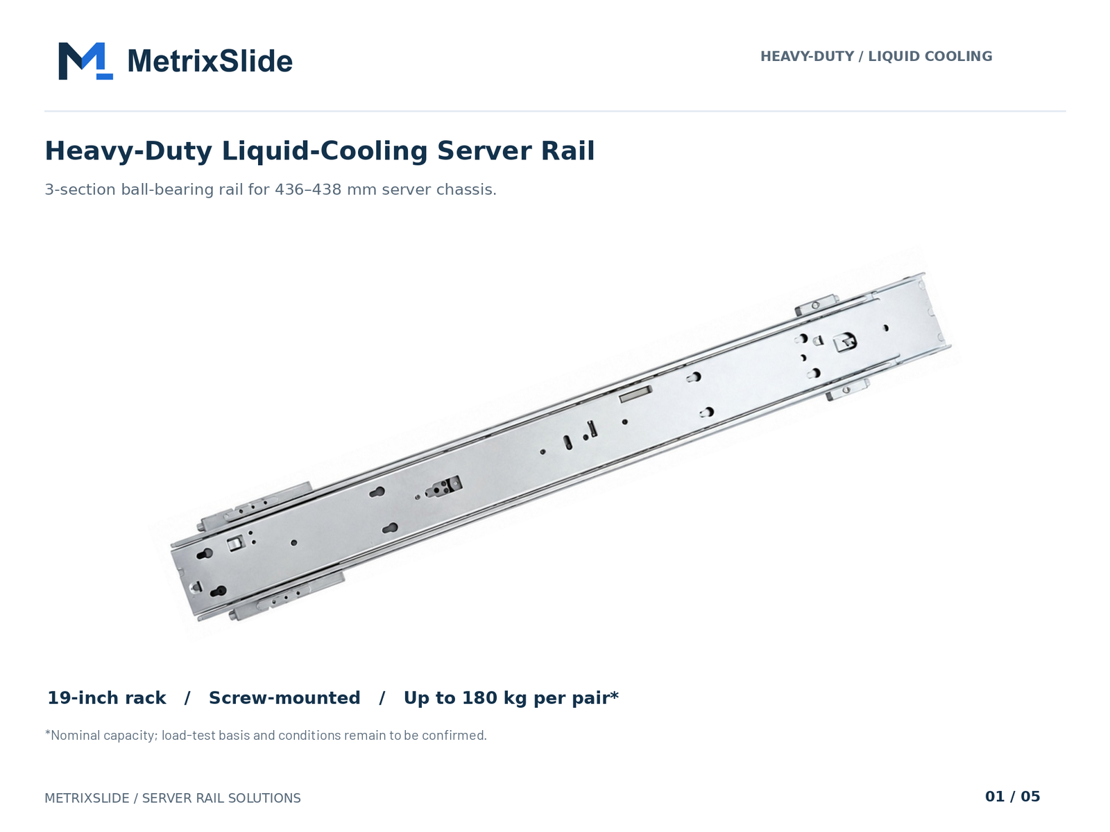 MS-BBR-180 Heavy-Duty Liquid-Cooling Server Rail — view product
Standardized step‑by‑step static load test procedure and fixture setup
A reproducible test procedure and recorded fixture CAD are the minimal commercial deliverables that prevent disagreements between supplier and buyer.
-
Sample receipt and pre‑inspection
- Verify part number, revision and visual condition against the packing list and the drawing revision history. Capture the drawing revision (and the file) that will be referenced in the test report.
- Dimensional checks: record closed length, full‑extension length and the bracket/fit range as shown on the drawing (closed/extended/bracket range are distinct values — do not derive one from another). Log stamping/hole‑position readings and any measured deviations.
-
Fixture design essentials
- The fixture must replicate the field mounting: use the same hole pattern and fastener types the rail is intended to accept (square punched + cage nut, round holes, or threaded posts — typical sizes appear in various projects, e.g., square 9.5×9.5 mm and round Ø7.1 mm in some customer interfaces, but always confirm the actual rack post hole spec).
- For telescopic rails, pin the outer member to the test rack and set the inner/middle members to the specified extension (full extension or the locked intermediate position) per the drawing. For fixed L‑bracket rails, secure the fixed member to the rack frame and load the chassis landing surface as drawn.
- Publish a front‑to‑rear EIA/IEC overlay on the fixture CAD so third‑party labs and customers reproduce the same post locations.
-
Loading blocks and load application
- Use rigid loading blocks that mimic the chassis contact area and transfer load to the intended support point on the inner rail. Locate them at the support points annotated on the product drawing (do not assume EIA hole grid spacing unless it is called out).
- Apply load with a calibrated actuator or dead weights and ramp gently to the target to avoid dynamic spikes. Record the rate and method of load application.
-
Dwell and termination criteria
-
MetrixSlide's factory static‑load test uses a 24‑hour dwell under load at full extension; document whether your acceptance criteria reference an equivalent dwell.
- Define and record termination criteria up front: visible fracture, a sustained load drop indicating failure, inner‑member jam (movement expected but not observed), or permanent deformation beyond the protocol tolerance. Because MetrixSlide has not yet published a universal allowable‑deflection limit, permanently specify any mm limits or functional thresholds in the protocol for that model.
-
Fasteners and torque control
- Use the fastener type the installation specifies; record thread type, hole type and the torque sequence used in the test. If the drawing does not specify a torque, use the fastener manufacturer's recommended torque and record that value for traceability.
-
Assembly order and reproducibility
- Document the exact assembly sequence and photograph each step. For telescopic designs note whether the inner member is removable and whether the chosen installation method is stab‑in or drop‑in (these sequences change how the load transfers and how lock‑out/pull‑out functions behave).
Practical items buyers should insist on
- A CAD of the test fixture with an EIA/IEC overlay and the exact drawing revision used.
- A complete fastener list, engagement lengths and washer/locking method used during the test.
- Numerically defined failure thresholds for the tested configuration (functional seating criteria, maximum allowable permanent deflection tied to chassis seating, or a percent load loss threshold), because there is no single industry allowable‑deflection limit that applies to all rails.
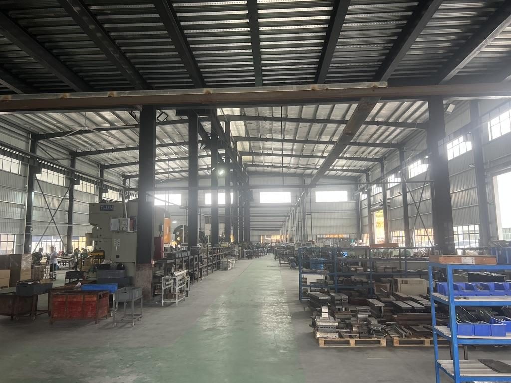
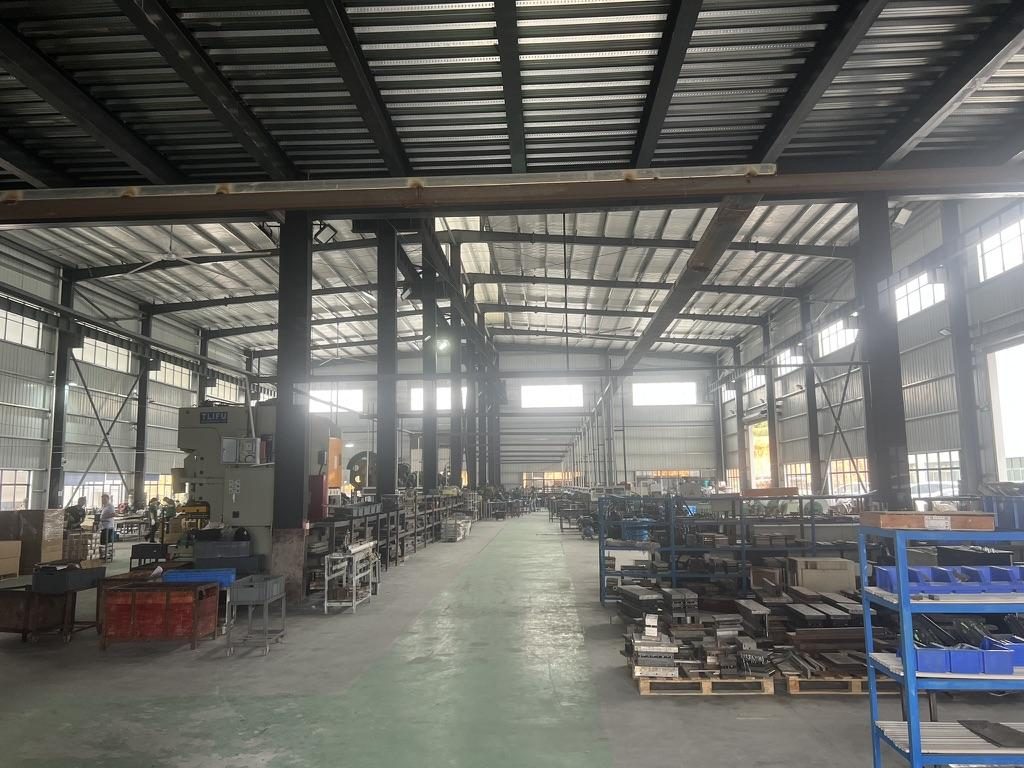 Overview of the server rail production workshop
Instrumentation, deflection measurement, calibration and repeatability
Credible results require traceable instruments and a documented uncertainty budget.
Sensors and placement
- Load: in‑line strain‑gauge load cell sized to the test range, installed in the actual load path between actuator and loading block.
- Displacement: LVDTs or laser displacement sensors for sub‑mm deflection; dial indicators can be used for simple checks. Typical measurements: mid‑span deflection of the inner rail under load, relative travel between telescopic members (to detect binding), and residual deflection after unloading.
- Strain gauges: full‑bridge gauges at predicted hot spots for local plastic strain detection when required.
Calibration and traceability
- Primary sensors must have calibration certificates traceable to a national standards laboratory. MetrixSlide maintains ISO 9001:2015 quality system records for slide processing; include sensor certificates and calibration dates in the test report.
- Define calibration intervals in the laboratory procedure and retain certificates with the test dossier.
Error sources and uncertainty
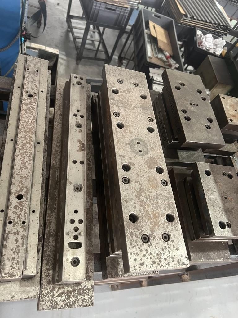
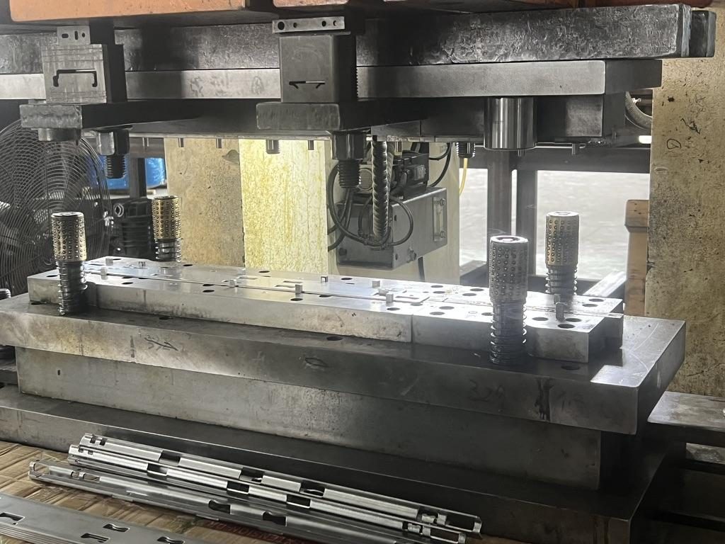
- Build an uncertainty budget covering load cell calibration uncertainty, displacement sensor accuracy, fixture compliance and manufacturing tolerances (hole position, stamping). For stamping precision, MetrixSlide's factory-level claim is that T‑pin / inner‑rail hole absolute error can be controlled to ~0.08 mm; validate this by inspection before using it as an acceptance gate.
- For production qualification use larger sample sizes. For a controlled acceptance test, MetrixSlide practice is to report repeated runs and the mean ± standard deviation; a minimum of three runs is common for a basic check, with more runs for statistical confidence where variability is expected.
Example data package to request from a supplier
- Raw time‑series data, filtered traces with filter descriptions, sensor serial numbers and calibration certificates, photos/video of the setup, the fixture CAD, and the drawing revision used in the assembly. These items allow independent FEA‑to‑test comparisons.
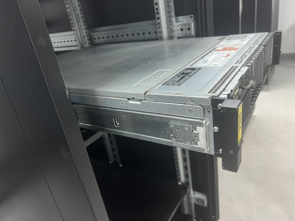
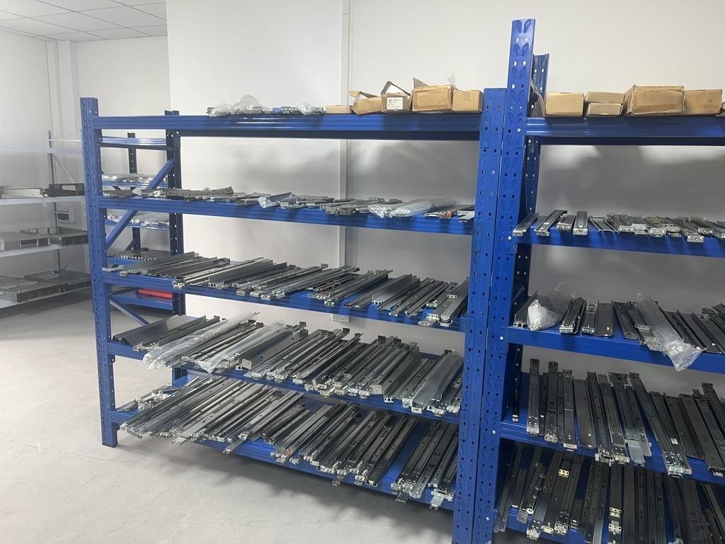 Sliding and fixed rail samples on the factory display rack
Acceptance criteria, common failure modes, test reporting and FEA correlation
Acceptance criteria should be unambiguous and linked to the intended functional outcome for the chassis.
Typical acceptance elements
- No catastrophic failure (fracture, torn welds or separations).
- A defined maximum residual deflection after unload (tied to the chassis seating function rather than a universal mm number).
- Functional verification: sliding action (no permanent binding), lock‑out engagement, and no fastener pull‑through.
Common failure modes
- Mid‑span bending/sag at full extension.
- Seat/panel pull‑out at attachment points.
- Fastener shear or thread stripping.
- Telescopic mechanism jam from ball loss or flange deformation.
- Weld or stamped tab failure under overload.
Test reporting essentials
- Test conditions: sample IDs, assembly drawing and revision, mounting frame CAD, fastener list and torque sequence, loading block geometry, extension state and target load.
- Instrumentation: sensor types, serial numbers and calibration certificates.
- Data and evidence: raw data, key events (ramp, dwell, unload), photos and video, and a conclusion that references each acceptance criterion.
- Maintain revision history for the drawing used and include the revision in the report so failures can be traced to the exact configuration.
FEA correlation
- Use the test to validate boundary conditions and material models. Compare mid‑span elastic deflection, strain at hot spots and the mode/location of yield. If FEA and tests disagree, inspect fixture compliance and contact definitions in the model.
Practical taxonomy and decision flow (MetrixSlide engineering practice)
Taxonomy (useful shorthand)
- Motion architecture: sliding vs fixed.
- Sliding mechanism: ball‑bearing vs friction.
- Mounting attributes: tool‑less vs screw; stab‑in vs drop‑in.
- Section count and extension: two‑section vs three‑section; closed vs full‑extension.
- Fit parameters: closed length, extended length, bracket/fit range (all three must be read from the drawing).
Decision sequence (hard gates before preferences)
- Compatibility hard gates:
- Chassis inputs: actual width, U height, depth and feature positions (T‑pin head/shaft/under‑head clearance).
- Rack inputs: actual front‑to‑rear post distance (or range), hole types and thread specs, and any special keep‑outs (e.g., busbars in OCP).
- If any of these do not match, resolve them before proceeding.
- Load hard gate:
- Required load vs validated model rating: confirm per pair vs per rail and the extension/test condition.
- Architecture and installation preferences:
- Choose sliding vs fixed, ball vs friction, tool‑less options, and whether stab‑in or drop‑in installation is required.
- CAD → sample → physical validation → performance test:
- Produce CAD for the chosen candidate, order samples and validate physical fit, then run performance tests. Passing CAD does not guarantee pass at performance.
Checklists to include with an RFQ (MetrixSlide standard intake)
- Chassis: STEP or DWG, U height, actual width, depth/engagement envelope, T‑pin data (head Ø, shaft Ø, under‑head clearance, positions/spacing), and expected load.
- Rack: post‑to‑post distance or bracket range, hole type (square/round/thread) and photos of posts.
- Desired installation: stab‑in or drop‑in, tool‑less preference, pull‑out/lock‑out requirements.
- Deliverables: required sample lead time, CAD format and revision control, and test expectations (e.g., 24‑hour static hold if required).
Anonymised project examples and how they change test needs
- A North American telecom OEM requested a 1U friction rail with reduced pull‑out and specific post‑distance requirements; during engineering the pull‑out requirement for load tests was reduced from a nominal 300 mm design down to an acceptance envelope of about 150 ±3 mm. That change affects fixture geometry and where the mid‑span loading block must sit during the static hold.
- An Indian HPC ODM specified a 2U server with a bracket range of 650–965 mm (their typical installations cluster near ~812 mm). When a bracket range is wide, fixture design must allow for the specific post distance intended for acceptance and the CAD must show the actual post distance that will be used in testing.
- A SaaS company building its own servers provided T‑pin details (PEM style) with head Ø = 6.502 mm, shaft Ø = 4 mm and under‑head clearance ≈ 1.585 mm; that datum set is used to derive inner‑rail J‑slot geometry for drop‑in installations and to produce keyhole retention tests. Always ask for the pin spec rather than an ambiguous "T‑pin".
- A Korean video‑surveillance OEM wanted an ultra‑slim rail for a 4U chassis with tight side clearances; in that program stamping precision and hole placement accuracy became a primary risk to installation and jamming, so dimensional inspection and controlled stamping processes were emphasised in the acceptance flow. MetrixSlide states its stamping absolute error capability, but buyers should obtain inspection reports as evidence.
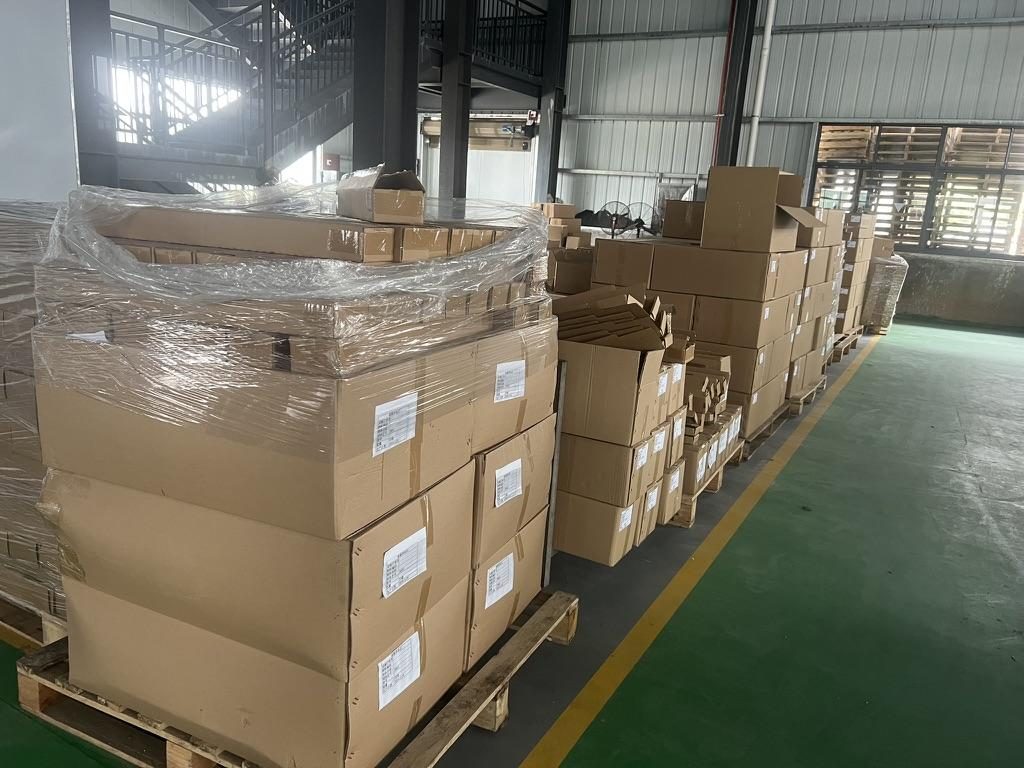 Export cartons of server rail kits ready to ship
Safety precautions, environmental effects, field testing and accredited labs
Operational hazards and controls
- Mechanical hazards include falling loads, clamp/fixture failure and stored energy in actuators. Use guarding, rated lifts for test weights and secondary catch blocks. PPE and an actuator emergency stop are standard controls.
- Environmental conditions (temperature, humidity, corrosion) can change friction behaviour and material yield — repeat critical tests at representative environmental ranges if the product will operate in extremes. If the product is intended for corrosive environments, specify finishes and include corrosion exposure in qualification.
Field testing and retrofit checks
- For in‑situ verification use conservative, minimally invasive checks: controlled lift under the chassis, monitor deflection, and torque checks on fasteners after installation. When retrofitting, document the assembly sequence and perform a limited static hold at a conservative fraction of the expected load before returning to service.
When to engage an accredited lab
- For formal acceptance or when a third‑party record is required, use an ISO/IEC 17025 lab or an NRTL‑recognized house according to the buyer's procurement rules. MetrixSlide can supply fixture CAD and sensor calibration certificates to support third‑party testing. MetrixSlide holds ISO 9001:2015 certification for slide processing.
Summary checklist for a buyer's test package
- Chassis STEP/DWG, exact T‑pin spec (head/shaft/clearance/positions).
- Rack post‑to‑post distance or bracket range and hole type photos.
- Drawing revision used for rails (include revision history).
- Fixture CAD with EIA/IEC overlay.
- Loading block footprint and intended load application point.
- Instrument list with calibration certificates.
- Defined acceptance criteria (functional and numeric ties to chassis seating).
- Requested dwell duration (if a 24‑hour static hold is required, state it).
Conversion / CTA
For static‑load testing, assemble a test package containing an EIA‑310 mounting overlay, recommended loading block footprint drawings, a torque‑sequence record, sensor mounting sketches and the numerical example above in tabular form. For laboratory validation, remote review of an assembly drawing, or an on‑site test plan review, prepare the same package and submit it to the reviewing lab.
U.S. buyers should coordinate third‑party ISO/IEC 17025 or NRTL‑recognized labs for validation and retain calibration certificates for in‑house sensors. Typical sample turnaround for a custom rail set depends on the drawing or mounting data submitted.
Contact: https://www.metrixslide.com/contact-us/ and https://www.metrixslide.com/page/create-a-quote/.
FAQ
Q: How do I calculate a conservative maximum static load per server rail from a manufacturer's total rack rating? A: Start by confirming whether the published rating is "per pair" or "per rail" and the extension state referenced. If it's per pair, divide by two for a simple per‑rail estimate, then apply a safety factor for field use (commonly 1.5–2.0) and confirm with the supplier’s test fixture and extension condition. Always verify the exact mounting and extension used to generate the published figure.
Q: Which ASTM, IEC or EIA/ANSI standards are applicable to static load testing of server rails and how do they differ? A: EIA‑310 (rack mounting dimensions) and IEC 60297 family define mechanical interfaces and U/RU sizing; ASTM/ANSI methods cover mechanical testing protocols in broader contexts, while UL/NRTL standards may add product‑specific safety requirements. For mechanical static load tests you will typically rely on your lab's method statement aligned to EIA/IEC dimensions and a documented acceptance protocol rather than a single universal ASTM test.
Q: What is the recommended fixture and mounting procedure for testing telescopic versus fixed server rails? A: For telescopic rails, pin the outer rail to a rigid frame and load the inner member where the chassis would contact, allowing the specified extension and recording binding behavior. For fixed L‑bracket rails, secure the bracket to the test frame and apply load to the intended support point; document fastener types and torque sequence in both cases so the test reproduces field clamps.
Q: Which instruments should I use to measure rail deflection and how often must they be calibrated for traceable results? A: Use a calibrated load cell for force and LVDTs or laser displacement sensors for sub‑mm deflection; strain gauges add local strain info. Primary sensors should carry calibration certificates traceable to a national lab (e.g., NIST traceability in the U.S.) and be calibrated on a scheduled basis (commonly annually or per lab procedure); include the certificates with the test report.
Q: What are the common failure modes during static load tests and how should pass/fail criteria be defined? A: Typical failures are rail bending/sag, seat or fastener pull‑out, weld/tab failure, and telescopic jamming. Define pass/fail quantitatively: allowable permanent deflection (e.g., mm), functional checks (no jam, locks engage), and no fractured parts; list these criteria in the test protocol before testing.
Talk to a MetrixSlide engineer
Want an engineer to run this check on your own chassis and rack? Send us a chassis drawing or model (STEP or DWG), the rack post-to-post distance and hole type, the expected load and your planned quantities. Within 24 hours you get a rail matching proposal from an engineer, followed by 2D/3D drawings for review and sample pairs (typically 15–20 days after drawing approval) for physical validation before the full order.
Bracket position, hole pattern, rail length and thickness adjustments on our existing platforms usually carry no tooling fee; structural redesigns are quoted separately with dies made in-house.